PMKS: Planar Mechanism Kinematic Simulator
PMKS returns quick and accurate results for the position, velocity, and acceleration of rigid bodies connected as planar mechanisms.
This project is maintained by DesignEngrLab
Creating a Four-bar Mechanism: Tutorial 1
In this tutorial, we will create a four-bar mechanism. You will use four-bar as a basis for many linkages. It is used for the crank-&-slider, and the six-bar mechanism described in Tutorial 2 and Tutorial 3.
1. From the start screen (http://purl.org/pmks/sim), notice the pendulum swinging around counter-clockwise at 10 rpm. Let us first change the speed to twice as fast in the opposite direction. This is accomplished by replacing the “10.0” in the speed box, with a -20.
2. Next, find the second joint in the table. Under the Links column, it only lists “input.” This is the name of the single link that is spinning around. Note that its x-y position is at {25, 0}, which corresponds to the open circle in the main viewer. As your mouse approaches the icon, the purple move arrow appears. Click and drag the joint to the y-axis – a point near {0, 50}. Feel free to click on the row and type 0 and 50 in the appropriate boxes. If you need to pan, use the arrow keys; if you need to zoom in or out, you can do this by the following methods:
Table 1: Shortcuts for zooming in &
out.
|
Mouse Wheel |
Keyboard |
Buttons in window |
||
Zoom In |
Forward |
PageUp, Home Add(“+”), or Insert |
|
|
|
Zoom Out |
Backward |
PageDown, End, Subtract (“–”), or Delete |
3. Add a new link to this joint by typing a new link-name on the line next to “input.” First double-click the cell and put a comma or space to separate the name from “input”. You can write anything for the name – use “coupler”, or your first name or simply the number “1” or the letter “a.” Note that the simulation stops and a faint shape appear at the end of the joint.
4. Add two more joints. This is done by writing in two more rows in the table. On a new row, add two link-names to the Links column. Ensure that one of them is the same name as your new name in Step 3; make up another name. Use the default “R (pin joint)” for all new joints. For the x-y position, put any values in. Now, add a fourth joint. Under the Links column, include your latest name and a second name which is either “ground” or “0”. Note that ground is a special link that must exist in your mechanism. PMKS_Web will likely correct common misspellings of ground as well. Once you finish putting in the new x-y position , you will likely notice movement. This is because you now have a one Degree-of-Freedom mechanism again and the simulation begins automatically.
Troubleshooting:
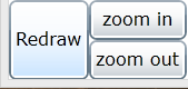
If you don’t have a four-bar moving on your screen and the DOF is not 1 –
make sure that you have not made a mistake in misspelling the link-names. If
the naming is correct and there is 1 DOF, try clicking the “Redraw” button in
the lower left.
5. Move the joints around and notice the changes in behavior. By now you likely noticed the three checkboxes at the end of the row and the one radio-button at the front of the row.
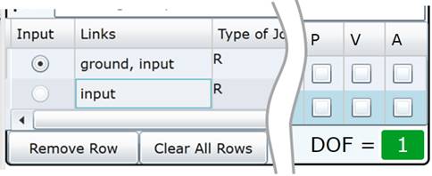
Figure 1: The left-most and right-most
part of the tables include check boxes for showing
the position (or path), the velocity and the acceleration of each joint. Also
the “Input”
column on the far left shows which ground link is driving the mechanism at
the speed shown
in the Speed box.
These “P, V, A” check boxes show the Path, Velocity, and Acceleration of the chosen joint. Check these to see the result in your mechanism. Note that the checkboxes have no effect for the grounded joints. You will also note in this figure the DOF shown in the bottom corner and buttons to remove rows in the mechanism.
6. Add one more joint to the mechanism (add one more row to the table) for a path-tracer point. Assign only one link. It should be the name you used for the non-grounded link. Move this new point around to see the coupler-curves. Be sure to click the “P” checkbox in this new row to show the green path followed by this tracer point. You mechanism might look something like this:
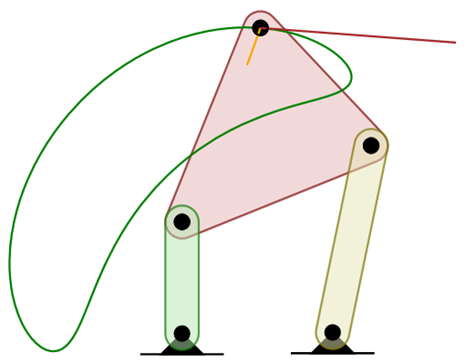
Figure 2: Example Four-bar created through this tutorial.
7.
Save your work. It is important to save your
work often, since this is a web program (and very must in beta development!).
There are two ways to do this: click the “Save Configuration” button, which
will say the details as a small text file; or click the “Get as URL” button.
This latter choice doesn’t save anything but rather generates a messy URL
that you should copy and paste somewhere else.
Check out other tutorials:
· Tutorial 2: Creating a Crank-and-Slider
· Tutorial 3: Additional Capabilities (n-Bar, Target Shapes, & Outputting Data)
Copyright ©2014 Matthew I. Campbell, Oregon State University Disclaimer