Methodology Overview |
|
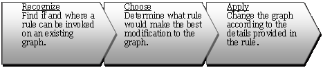
Graph transformation systems, or graph grammars, is branch of graph theory research that rigorously defines mathematical operations such as addition and intersection in graphs. Mathematicians have developed the foundations of this research, and engineering design researchers have appropriated the concept to formalize the creation of complex engineering systems. Electric circuits, truss structures, and chemical processes are just a few of the artifacts of engineering design that are easily represented by graphs. When viewing the artifact as a graph constructed from an initial simpler graph that describes the problem, one needs to develop a set of rules to capture the valid transformations that can occur. The grammar rules, organized into rule sets are then subject to a generation process. This process has three step steps: recognize, choose, and apply as illustrated in Figure 1. |


|
Figure 1: For creative systems, we consider three distinct steps of 1) recognizing what rules are applicable, 2) choosing one of these rules to apply, and 3) the application of the rule which involves a graph transformation of the host to a newly synthesized state. |
RepresentationRules and graphs in GraphSynth are stored in an XML format and are loaded into the program and instantiated as define graph object: nodes and arcs. Grammar rules are essentially constructed of two elements: application conditions (that, if met, are valid transitions in the state-space tree), and application instructions (how the graph is to |
|
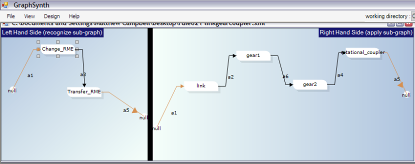
Figure 2: Two example rules created with GraphSynth: a) this first rule is from sheet metal research, where a patch of sheet metal is removed by a side notching operation. In addition to drawing the graph in GraphSynth, the designer can also change important parameters within the properties window. b) The second rule is created for the research on NSF Grant IIS-0307665 (Creating a Computational Theory for Conceptual Design) wherein function structure elements are replaced with real components.. |
|
(b) |
|
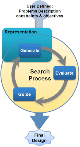
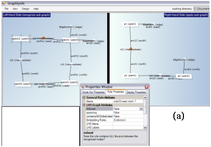
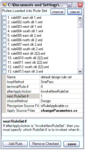
A rule set is essentially a set of rules that capture the space for a particular design problem. In implementing rules, the researchers have discovered that many applications require more than one rule set . Furthermore, when the number of rules becomes large it is easy to create inconsistencies amongst the rules. Therefore we allow for multiple rule-sets to capture the entire space of solutions. Figure 3 represents the graphical view of a rule set. These are described in more detail here. The Big PictureWithin the source files of GraphSynth, you will find the details for classes like grammarRule.cs and ruleSet.cs are stored in the folder named “1.Representation”. The other main folder are : “2.Generation”, “3.Evaluation”, “4.Guidance”, “XMLandIO”, and “Display Forms.” The authors of GraphSynth theorize that the division of representation, generation, evaluation, and guidance is useful in almost all computational synthesis methods. This generalization can be captured by the flowchart shown in Figure 4. The representation is formulated by the programmer of the computational design method to capture the forms or attributes of the design space. For example, in genetic algorithms, the representation is usually a bit-string that represents the key decision variables in the process. Using this representation, candidate solutions are |
|
Figure 3: An example Rule-Set from the sheet-metal research. In addition, to the rules contained within a rule-set, there are additional properties such as how the rule-set terminates, and what additional rule-sets are to be invoked. |
|
generated in the generation task. In genetic algorithms, this is done by mutating and “crossing over” existing or parent candidates. Each generated candidate is evaluated in the evaluation task to determine how well it meets the objectives and constraints of the design problem. Based on the objectives calculated for the candidates a guidance strategy is implemented to inform the search process of how to find better solutions in the subsequent iterations. In genetic algorithms, this is the “survival of the fittest” tournament selection where candidates with inferior fitness values are removed from the search process. Other than these four folders in GraphSynth, the folder named XMLandIO and DisplayForms deal with the saving and loading functions and the user interaction windows, respectively. Other than these, there are three C# class files not contained in a directory. The Program.cs file is the static class that is the main entry point for the application. The candidate.cs file contains the details of a candidate solution which is basically what is being moved about the four aforementioned modules. A candidate contains a graph, of course, but also other information useful when performing automated search processes. Earlier, a description of the basic representation classes was provided. GraphSynth also provides a clear way that graphs are created through a main generation class. The details of this are described here. |
|
Figure 4: The generic flowchart for Computational synthesis has four basic divisions: a representation of the design space, a method for generating new solutions, a method for evaluating solutions, and a method for guiding the search process. |
|
There is little that is found within the Evaluation and Guidance folders other than placeholders for an example search process. For a particular application, one would create their own evaluation methods, and thus there is no general methods that can be provided for this. For guidance strategies, there are currently no such methods for graph synthesis. Our current research is developing a number of these. In the meantime, GraphSynth can be use to synthesize graphs, either through user-guided or random decisions. Future updates will include guidance methods, and thus a full optimization procedure can be made to design optimal graph topologies. |