PMKS: Planar Mechanism Kinematic Simulator
PMKS returns quick and accurate results for the position, velocity, and acceleration of rigid bodies connected as planar mechanisms.
This project is maintained by DesignEngrLab
Creating a Crank-&-Slider Mechanism: Tutorial 2
|
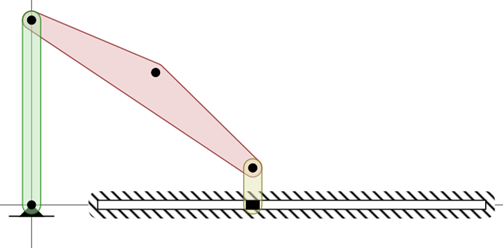
This tutorial will define a very popular mechanism referred to as a crank-slider. It is simply done by changing one of the revolute (R) joints from the four-bar to a prismatic slider (P). 1. Open the four-bar you created in the first tutorial by clicking the open button in the upper left. If you didn't save one, you can start with this one. Click here to get to the simulator. 2. Set the last joint from the “R” joint to a “P” joint. This is the link that is connected to ground – not the tracer point made in step 6 of the first tutorial. You should see something like this:
Note: that the “P” joint requires an angle to be provide for it to be properly specified. Indicate in the Angle column a value in degrees. Typically values can range from -90° to +90°. 4. In addition to specifying the angle and position in the table, one may also click and drag the icon. Click on the purple arrows to move the joint in x & y or click on pink arrows to rotate the slide. Note: you are not having to catch the moving link! You manipulate the unfilled icon that appears at the initial location.
5. On the far left of the table, you can change the input or the driving joint in the mechanism to any joint connected to ground. This applies to “P” joints as well. Click the radio-button in the row for your “P” joint. What happened? Hopefully, the mechanism is moving but it might be moving at a different speed. Note how the text above the speed box has changed from rpm to units/sec. Now the input is to move the slider at the designated velocity. The “units” can be thought of as either inches, or mm. 6. Set that link back to an “R” joint to return to a four-bar. Now, let us set one of the non-grounded joints to a “P” joint. This essentially creates an inversion of a crank-slider. Don’t forget to specify an angle. You might have a new mechanism that looks something like one of these:
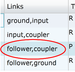
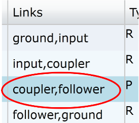
7. Note how the slider is one link and the other link connects to the fixed block. This is not arbitrary. It depends on the order of the link-names as provided in the “Links” column. Try switching the order. For example change:  to to
 7. Additionally, you can try replacing other R joints with P joints, but beware of the following constraints: a. The simulation will not be able to start if any P joints are at the same angle. This is because at this starting point there is an additional degree-of-freedom that cannot be handled. b. You cannot have a 4-bar with only one “R” joint as the rotation of this single “R” will need to be accommodated by some counter-rotation in another R joint. PMKS will indicate this as a zero DOF mechanism. c. You cannot make a mechanism consisting of four P joints. This will have 2 degrees of freedom, but you can make a mechanism with 3 links and 3 joints. Check out other tutorials: · Tutorial 1: Creating a Four-Bar · Tutorial 3: Additional Capabilities (n-Bar, Target Shapes, & Outputting Data) Copyright ©2014 Matthew I. Campbell, Oregon State University Disclaimer |
 Figure
1: Example Crank-Slider.