PMKS: Planar Mechanism Kinematic Simulator
PMKS returns quick and accurate results for the position, velocity, and acceleration of rigid bodies connected as planar mechanisms.
This project is maintained by DesignEngrLab
Additional Capabilities: Target Shape, n-bars
and Outputting Data: Tutorial 3
|
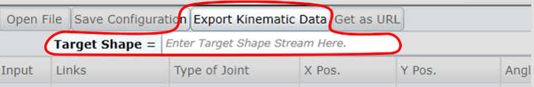
This tutorial will focus on some of the additinoal capabilities that are useful for designing and analyzing mechanisms in PMKS. 1. Let us start with the same four-bar mechanism that was created in the Tutorial 1. Open the four-bar you created in the first tutorial, or if you didn't save one, you can start with this one. Click here to get to the simulator. 2. In order to design a mechanism it is useful to have some additional shapes or frames of reference appear on the screen. In the current configuration, these are added through the Target Shape box near the top of the joints table.
This currently supports vector drawings in a rather simple compact format that is described at here: Path Markup Syntax. Here are some example shapes that can be used to define target paths.
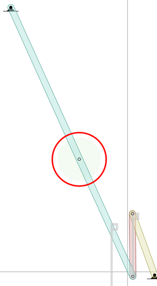
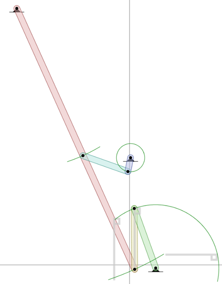
3. Consider this last case. After applying three-position synthesis, we may be lucky enough to arrive at a functioning four-bar like this one. However, since it is a double-rocker, it won't likely be actuated by a continuous motor. This is often and easily remedied by designing an additional dyad to drive the mechanism through this path. With this mechanism, let's add three more joints and two more links. 4. We only need to move the long input link about 10 degrees. In order to do so, add a new joint about halfway along the link with a new coupler name, like c2. See Figure 2 below. (This is intentionally left vague to test your knowledge from Tutorial 1).
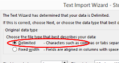
5. Now add two more R joints to make an input crank like the figure above on the right . Be sure to change the input column radio-button so that this new grounded crank is the input. Congratulations, you've just made a Watt II six-bar mechanism. 6. In order to get a more detailed understanding of the movement, one might prefer to export the data to Excel or Matlab. This is easily done by clicking the "Export Kinematic Data" button shown above in Figure 1. This will create either a tab-delimited .txt file or comma-separated .csv file to your desktop. You are welcome to change the name, but it should be uniquiely identified by its time-stamped filename. Let us save this as a .txt file. 7. Now, let's open this txt file in Excel. First open Excel and then Excel's open dialog. Note: you will have to tell Excel to show other file types to find this file. When faced with the import wizard, choose delimited (as shown below), and indicate that the 'delimiters' are tabs and/or commas.
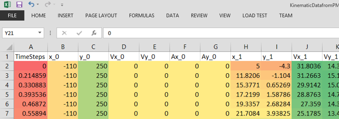
8. The table is organized with rows indicating the time steps and columns for all of the joint and link state variables. Following the order of joints in the table, the columns will correspond to: joint1's x-position, joint1's y-position, joint1's x-velocity, joint1's y-velocity, joint1's x-acceleration, joint1's y-acceleration, and so on for the next joints.
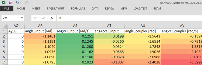
9. Next, the table will have columns for the link data. There will be three columns for each link: angle (in radians, NOT degrees), angular velocity (in rad/s), and angular acceleration (in rad/s2). Use these values for making plots as a function of time or searching for peak values in the movement.
Check out these tutorials: · Tutorial 1: Creating a Four-Bar · Tutorial 2: Creating a Crank-and-Slider
Copyright ©2014 Matthew I. Campbell, Oregon State University Disclaimer |